
A multiplexed narrowband RGB light source
A multiplexed narrowband illumination offers several advantages over traditional broadband white light sources:
Reduction of chromatic aberrations
Chromatic aberrations are caused by different wavelengths focusing at different depths. Using narrow-band wavelengths results in sharper, more accurate images.Higher color saturation and contrast
Narrow-band light ensures that each color channel on the sensor is illuminated with minimal pixel crosstalk. This leads to more vivid colors, and high-contrast images.Customizable wavelengths selection
With the right combination of LEDs and filters it is possible to select specific wavelengths. These can be selected to match the peak sensitivity of the camera’s Bayer filter, maximizing signal-to-noise ratio and color accuracy.Monochromatic illumination
When each LED channel is electronically controlled, it is possible to cycle through each independent wavelength to bypass all artifacts caused by the Bayer filter of the camera.
Results
Before anything, here are some results to compare between white light, combined wideband RGB and narrowband RGB.
Everything was captured directly from the raw stream of the camera.
Original colors are unprocessed (Gimp > Colors > Auto > White Balance).Adjusted colors are using the “Levels” tools from gimp.
A quarter resolution debayer was used.
Focus stacking was used.
Objective used is an Olympus MPlanFL N 5x/0.15 with BH2-MA tube lens.
This is far from an optimal combination and will induce more chromatic aberrations.
Nonetheless, narrowband monochromatic illumination is able to fix everything.
White light
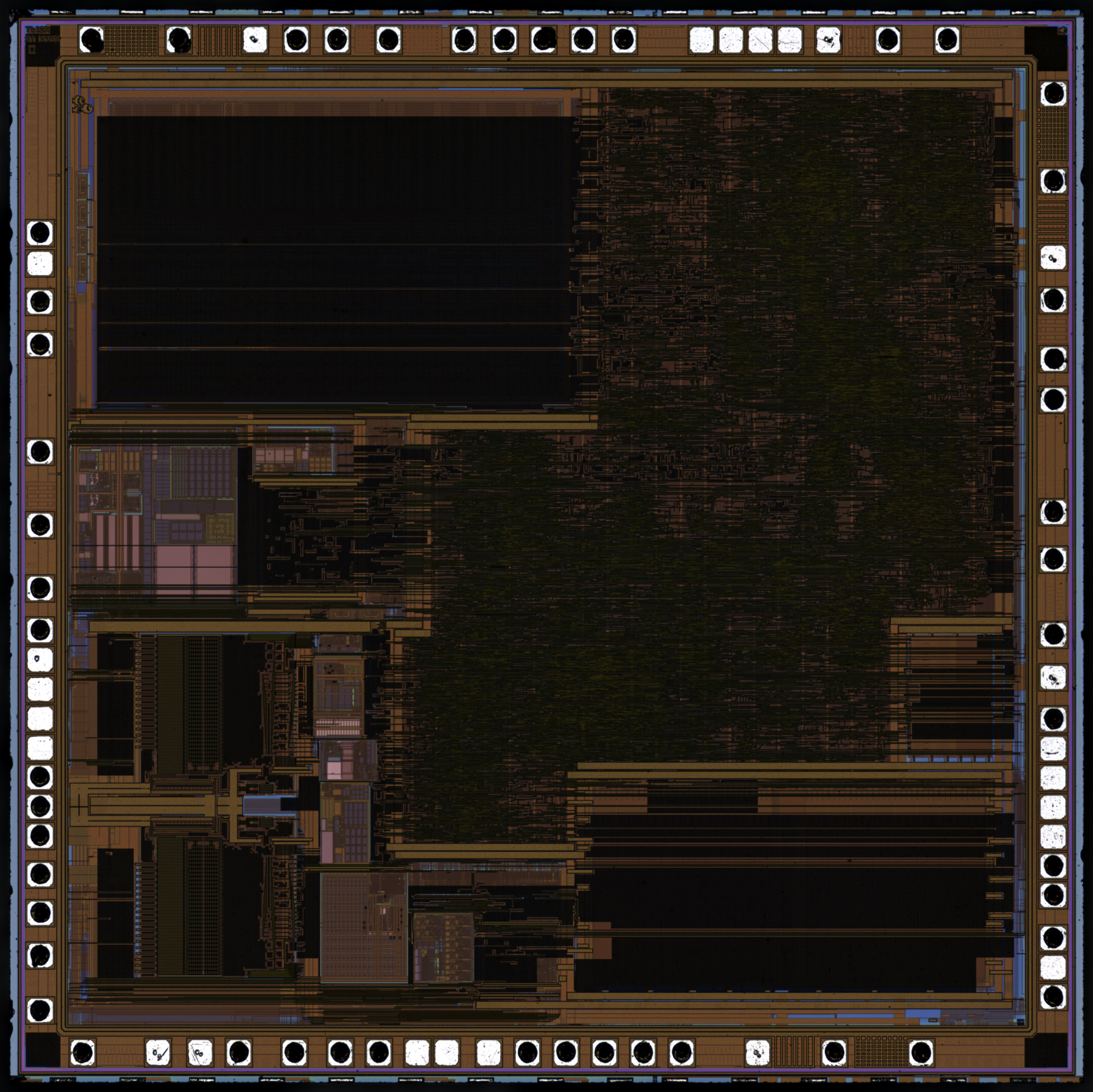
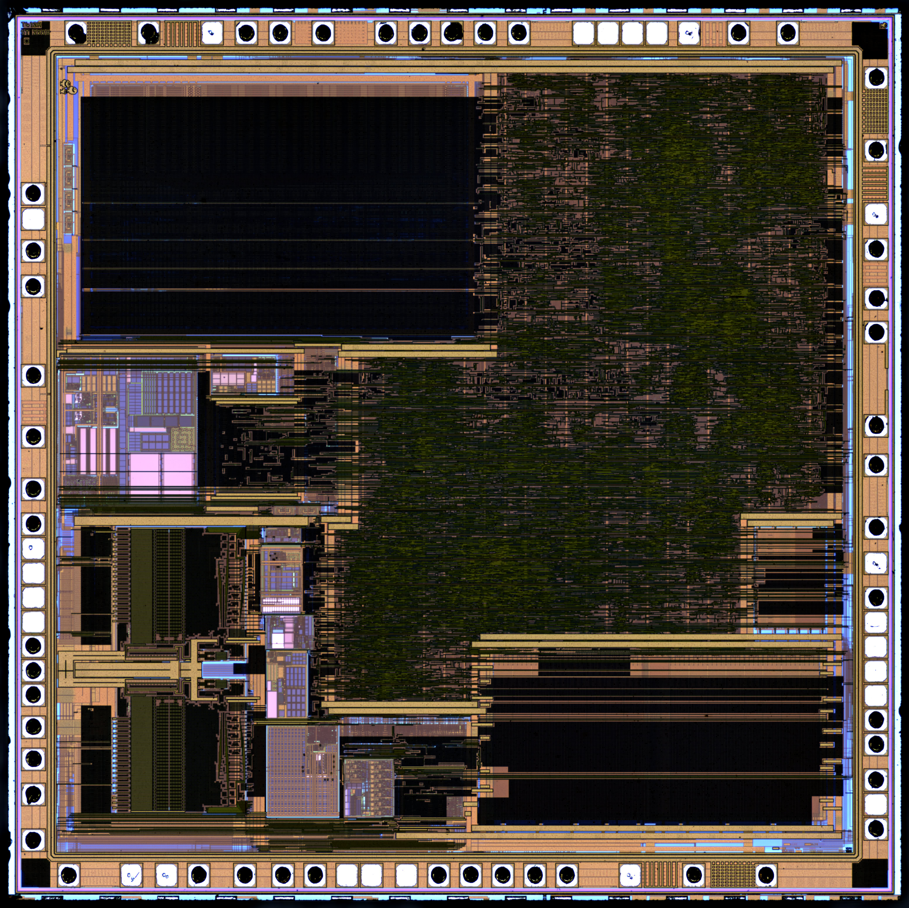
Multiplexed wideband RGB
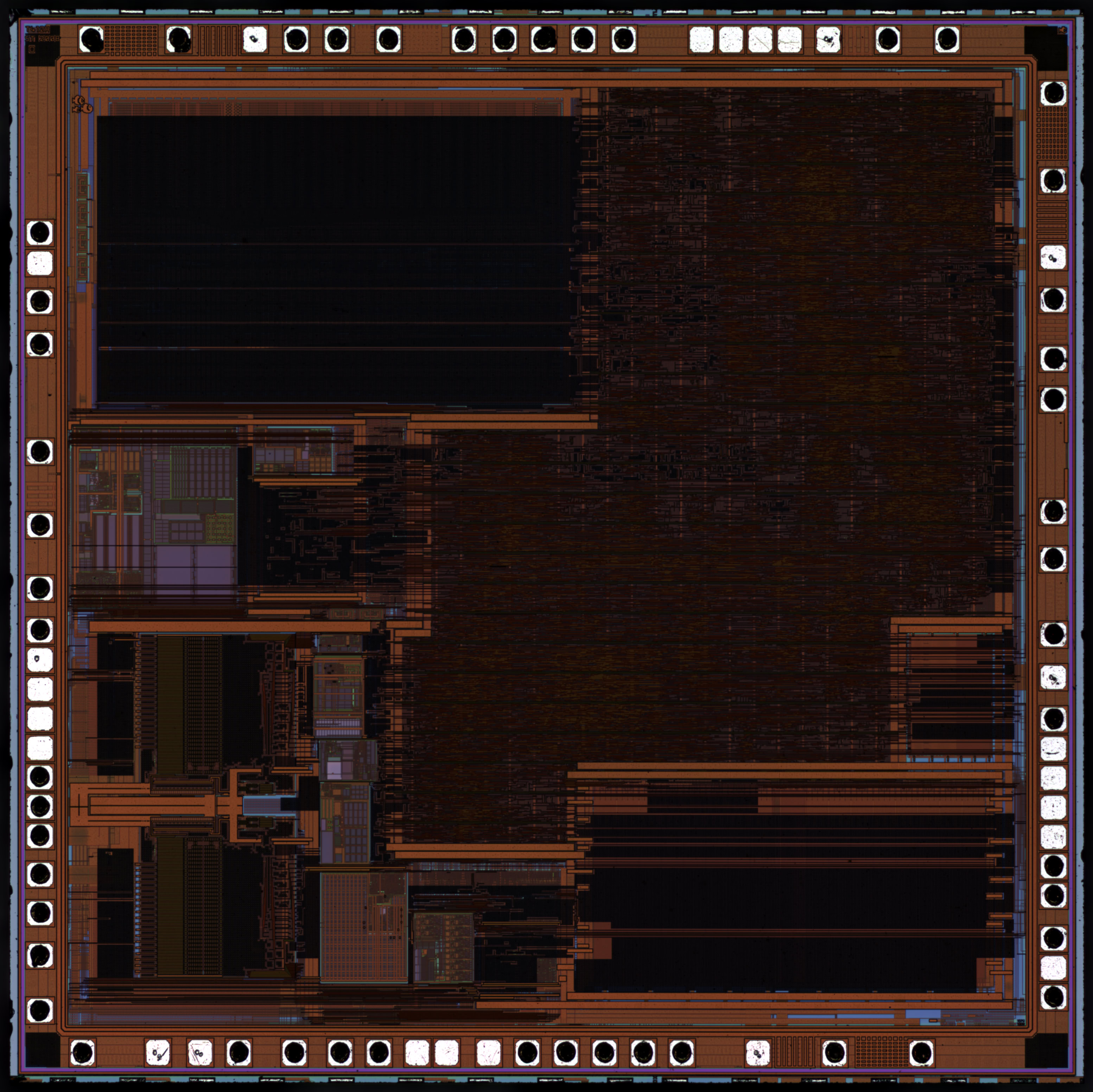
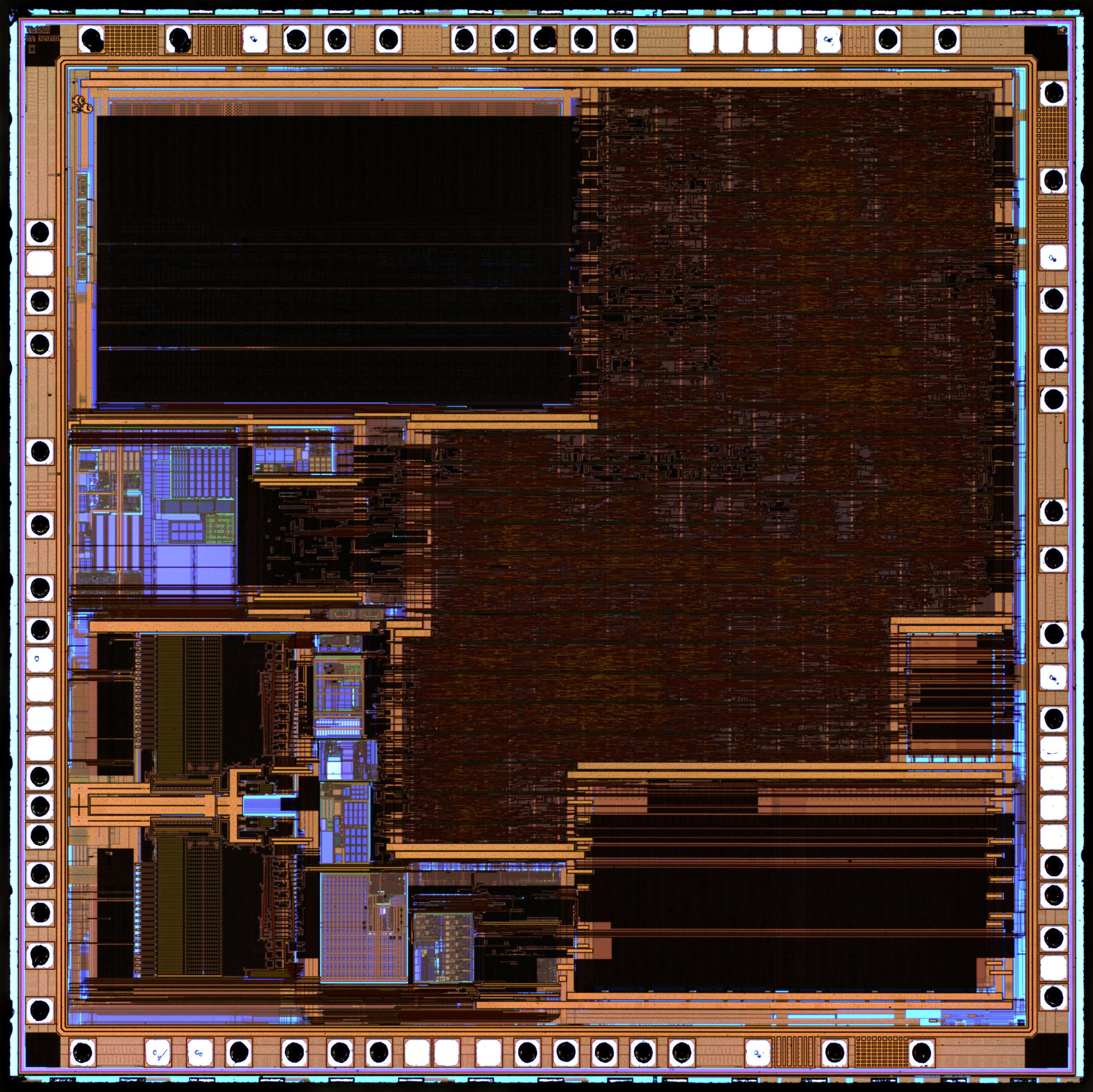
Combined monochromatic wideband RGB
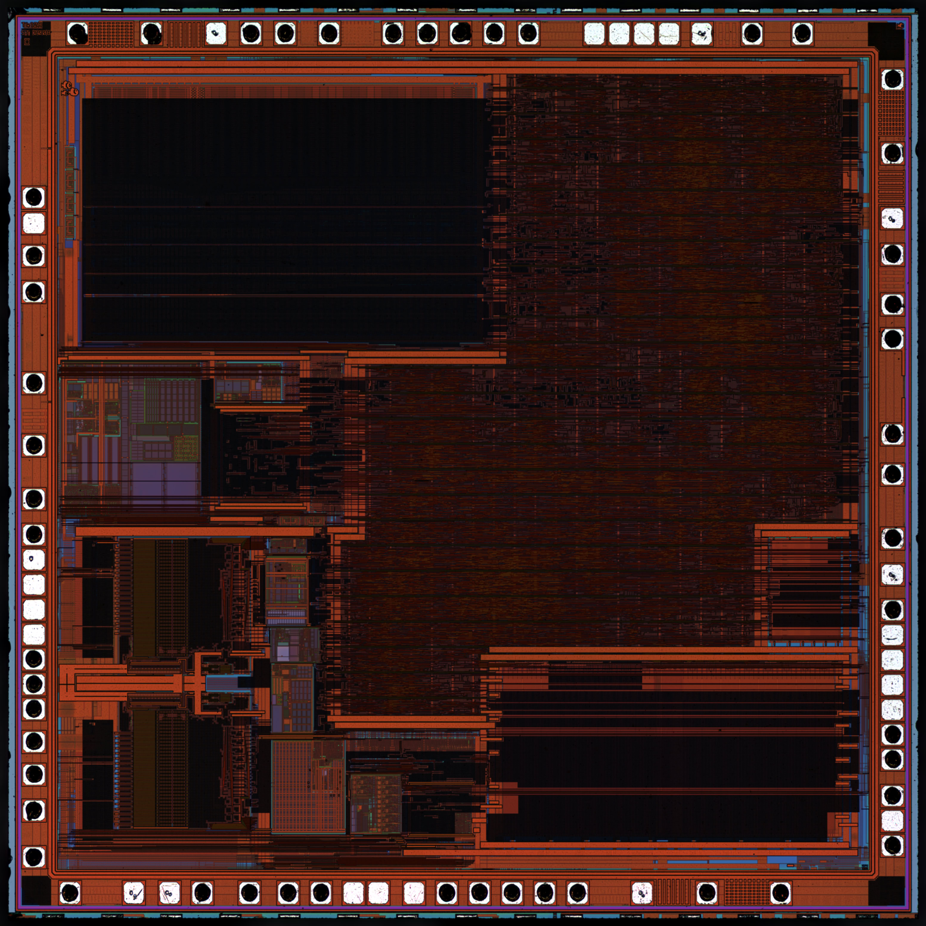
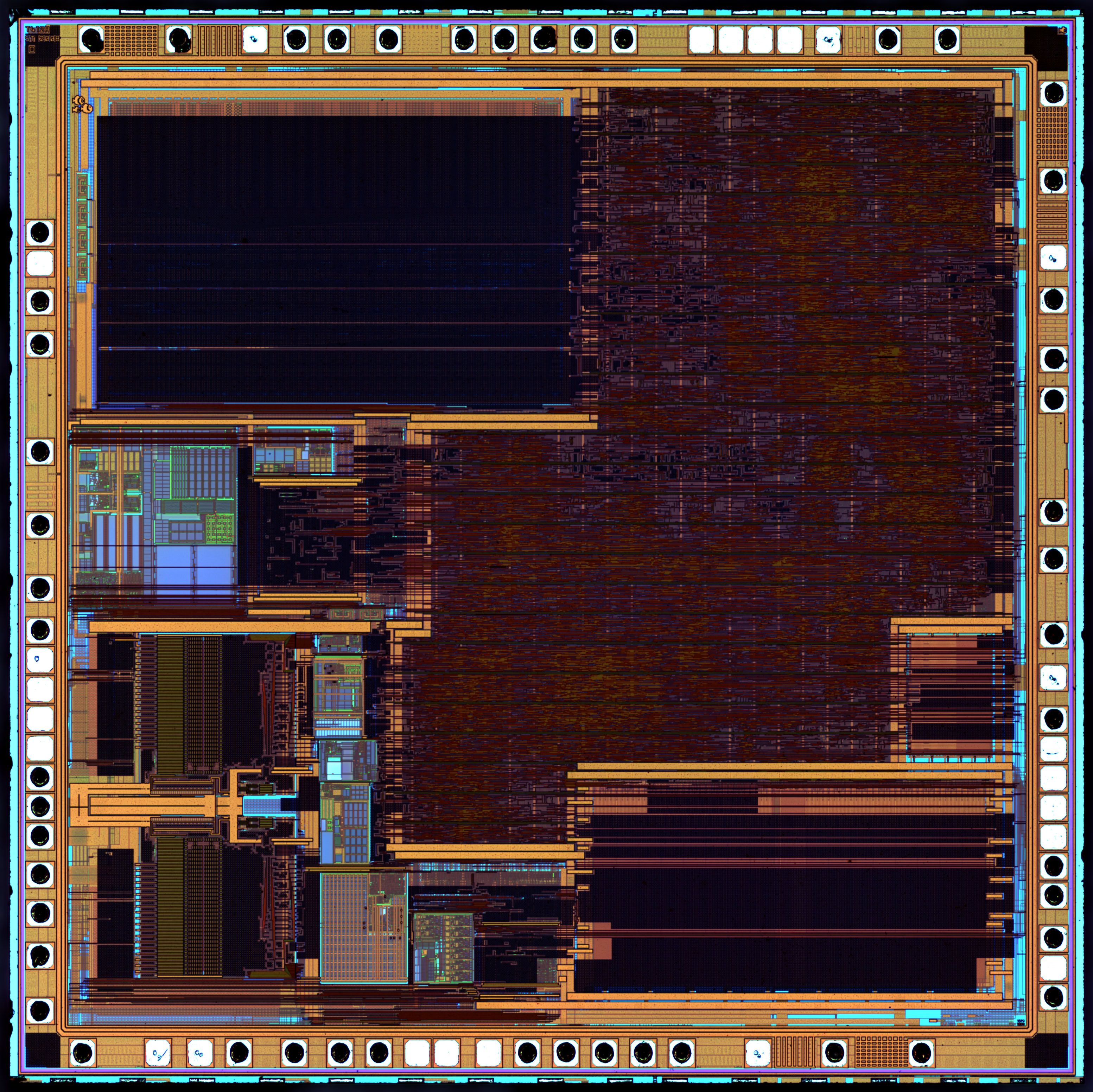
Multiplexed narrowband RGB
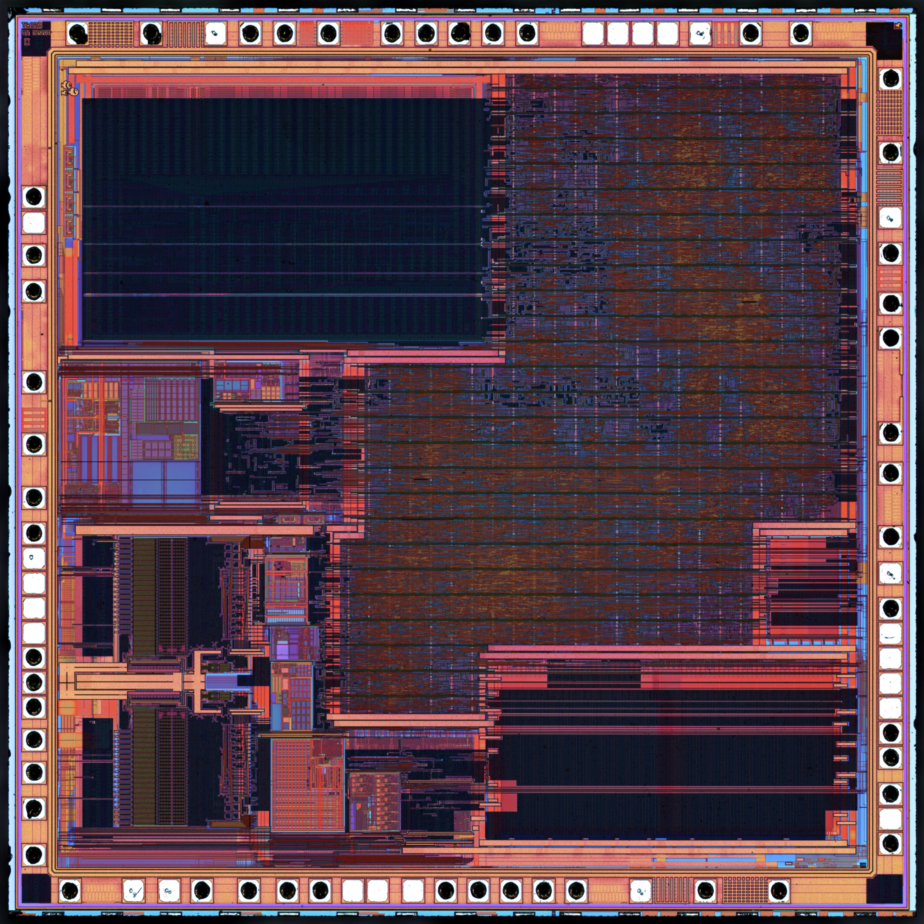
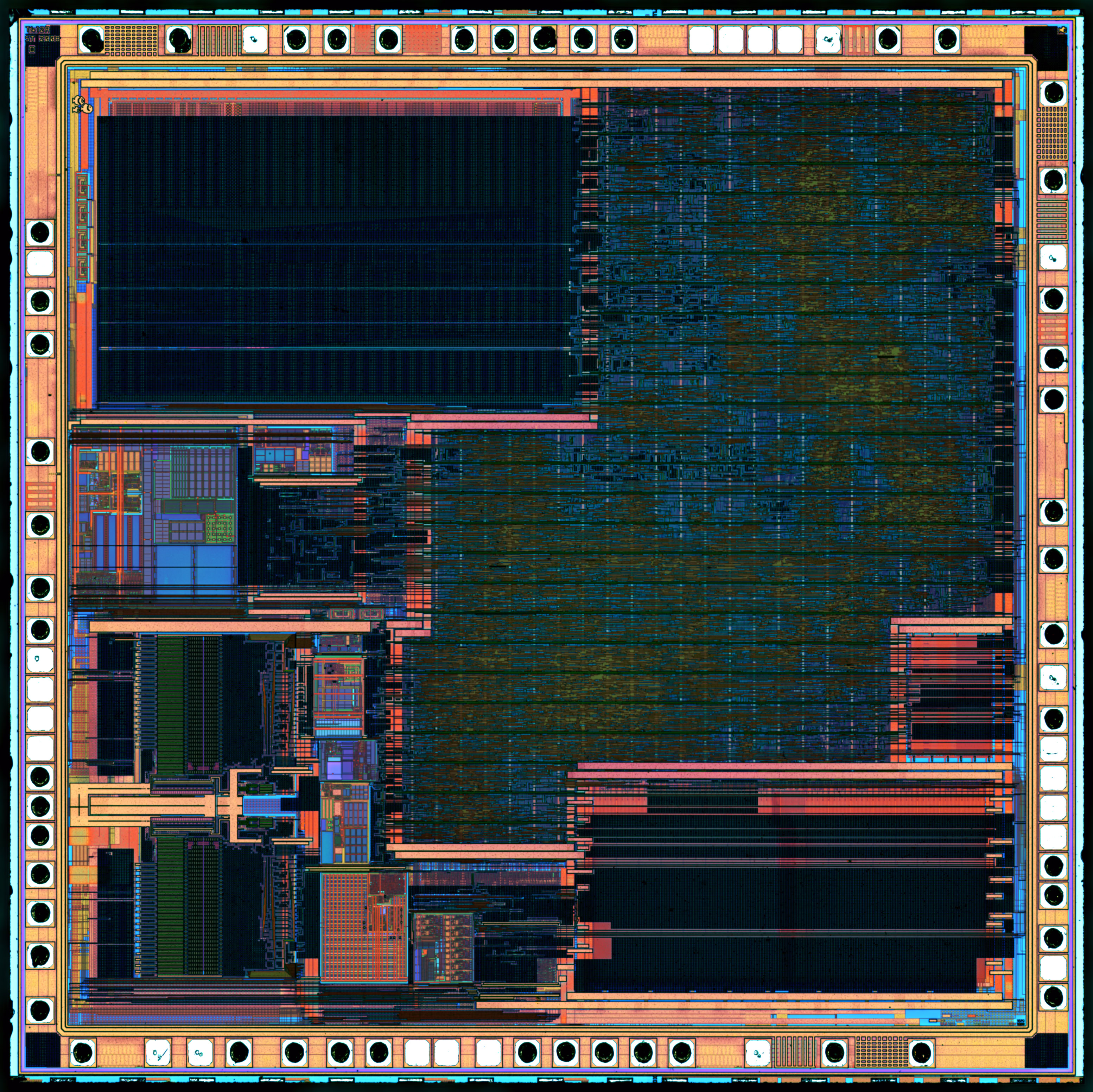
Combined monochromatic narrowband RGB
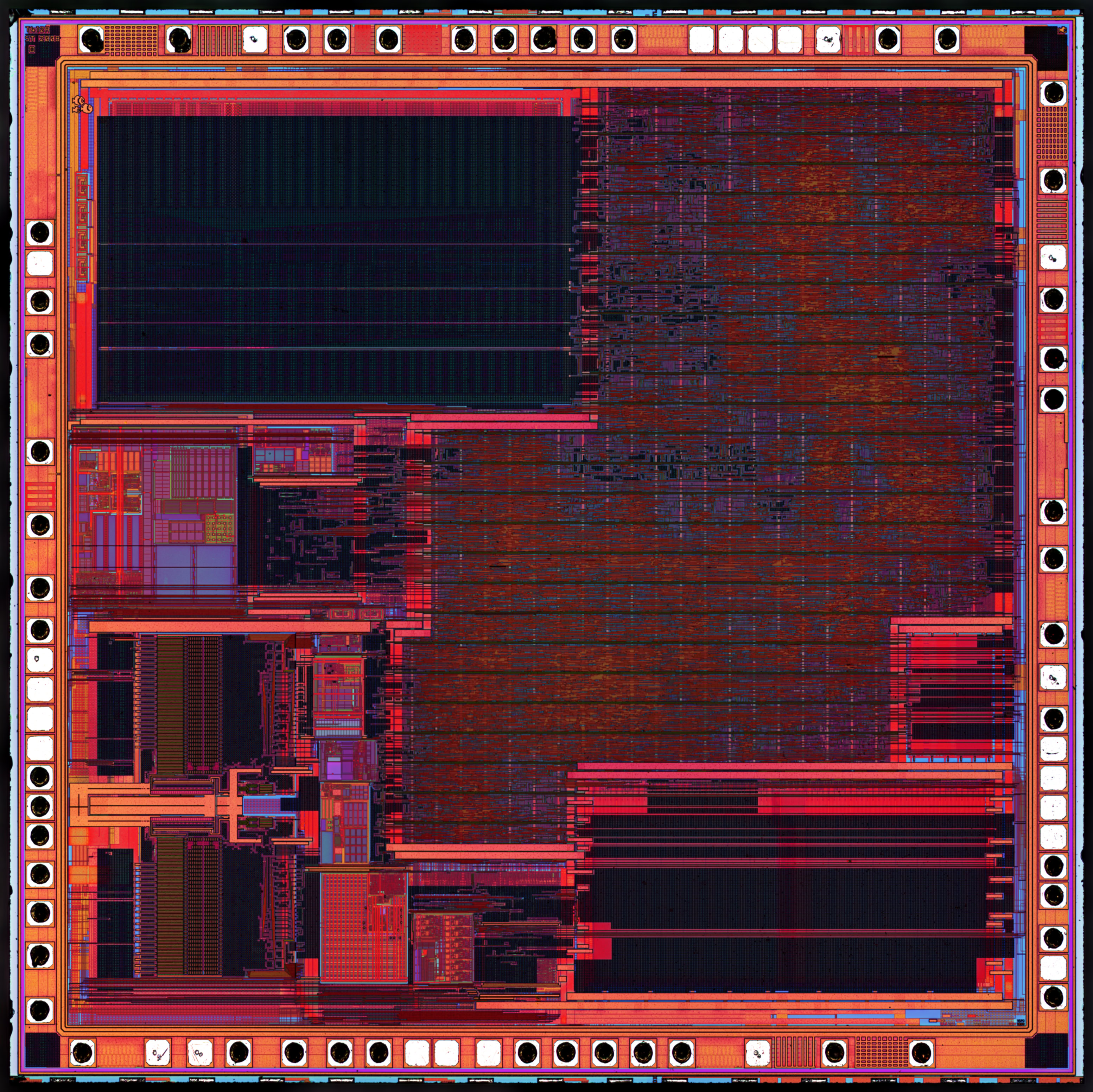
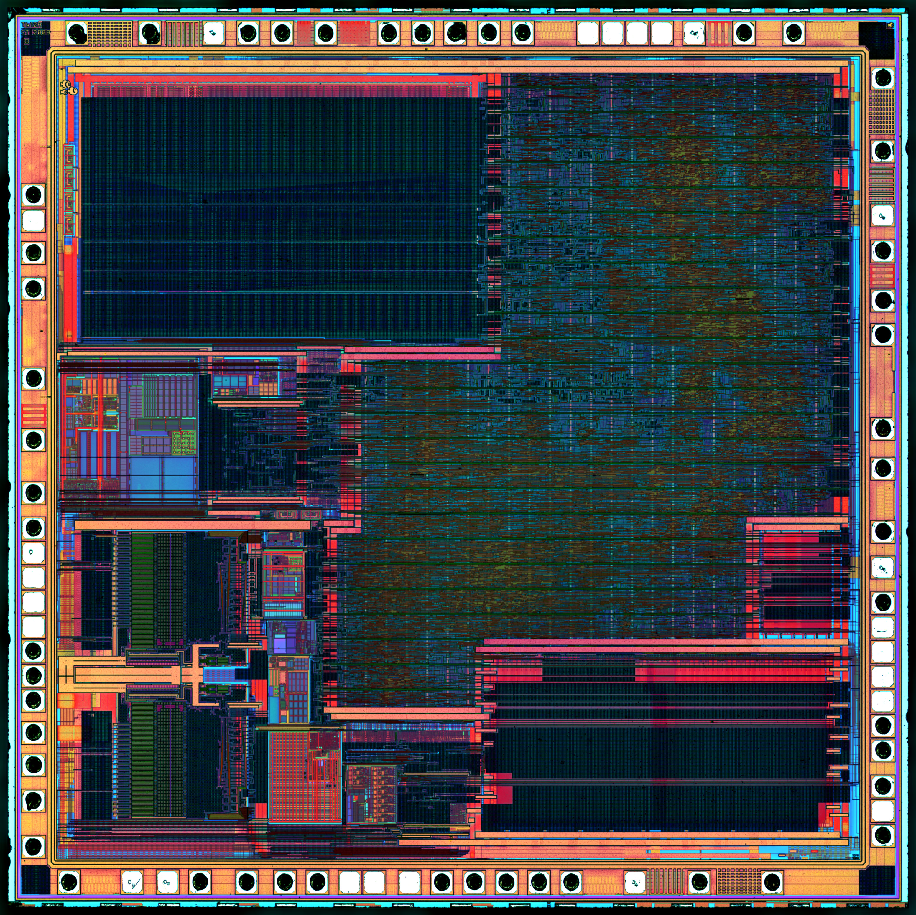
We can clearly see that the narrowband RGB light (FWHM = 15nm) gives much more colorful images. Combined monochromatic images also have higher saturation than with multiplexed RGB.
With combined monochromatic narrowband light and the right combination of wavelengths, it is possible to get impressive results:

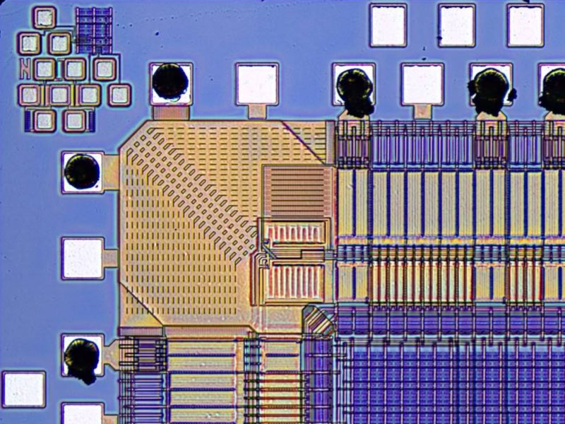
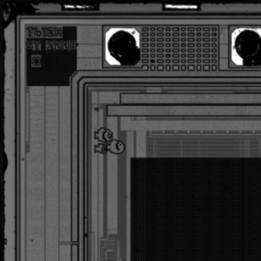
STM32F103C6T6A in false colors.
R=446nm, G=550nm, B=660nm, FWHM=15nm
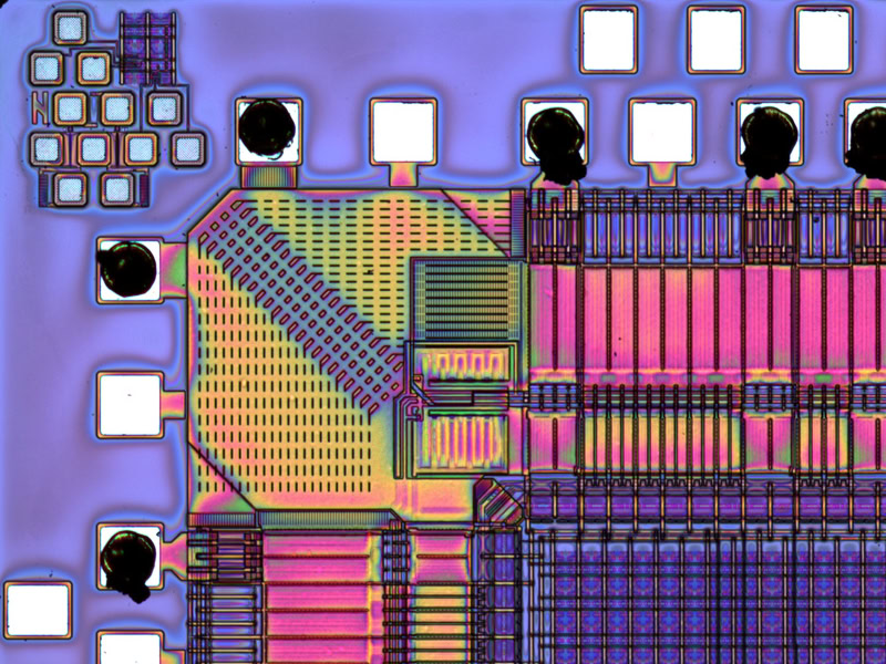
Thin film interference
With narrowband RGB illumination, interferences have much higher contrast than with white light.
Results in the blue wavelengths
The most impressive results are in the blue wavelengths.
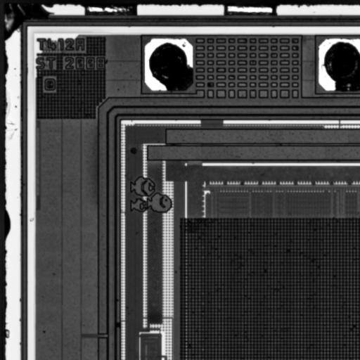
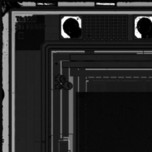
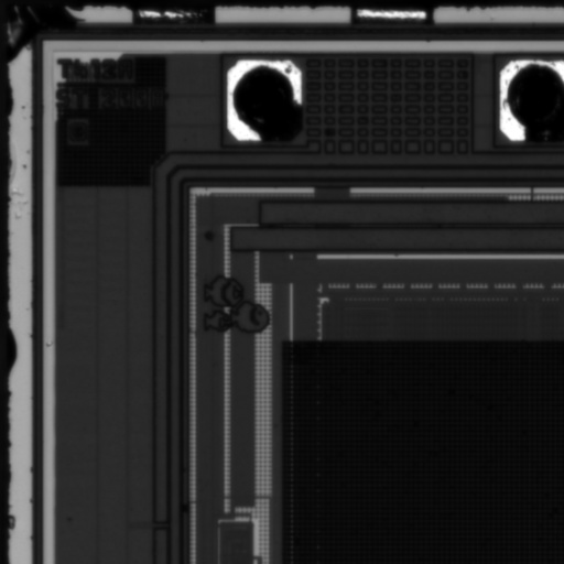
We can see that using a blue led instead of white light will not improve results by much. It’s still very hard to read the text on the corner.
But combining the blue led with a narrow bandpass filter give results looking as good as using an apochromatic objective.
Bypassing bayer filter limitations

Sony IMX477 Spectral sensitivity characteristics
Bayer filters on CMOS sensor are wide (about 100nm).
If we look at the sony Sony IMX477:
| Channel | λ1 (Start) | λ2 (End) | FWHM | |||||
|---|---|---|---|---|---|---|---|---|
| Blue | 400 nm | 505 nm | 105 nm | |||||
| Green | 478 nm | 598 nm | 120 nm | |||||
| Red | 580 nm | 700 nm | 120 nm | |||||
| B/G crosstalk | 472 nm | 512 nm | 40 nm | |||||
| G/R crosstalk | 576 nm | 614 nm | 38 nm |
FWHM: Full Width at Half Maximum
With traditional illumination, wavelengths will leak and mix through the bayer, in the overlapping regions of the spectral sensitivity graph.
This has several negative consequences:
Desaturated colors
Pixel crosstalk of the Bayer will leads to flatter, less vibrant colors.Ghosting
Lateral chromatic aberrations and spectral leakage can cause one color channel to “bleed” into another, resulting in ghost images and degrading overall image quality.Reduced resolution
For non-apochromatic objectives (which are not corrected for chromatic aberrations across the full visible spectrum), different wavelengths focus at different planes. This can significantly degrade spatial resolution with broadband light.
RGB multiplexing
There are several ways to mix different LEDs.
Beam splitters
A solution is to use two beam splitters, but there will still be 2/3 of the light lost.Optical fiber
Zeptobars is using optical fiber but this is suboptimal and most of the light is lost.Dichroid mirrors
The most efficient solution is to use dichroid mirrors. In this case almost no light is lost, but the mirrors have to match the LEDs and may be expensive.
I’m using another solution, easy to build and inexpensive if you can find a dead 3-LCD projector.
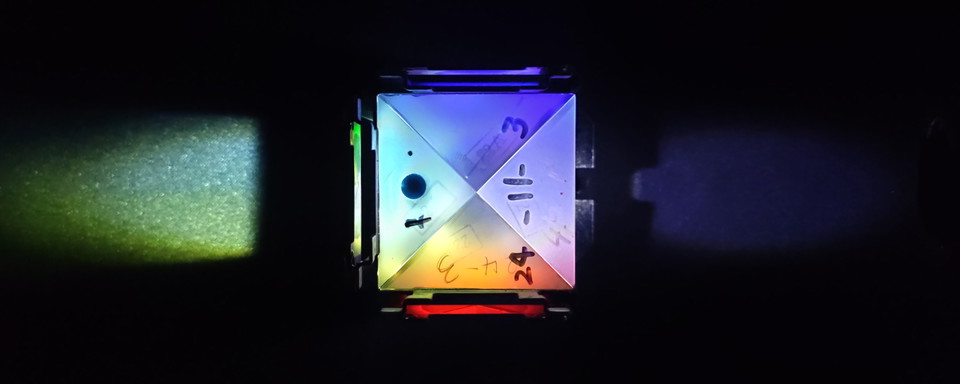
X-Cube RGB light
An easy solution is to mount colimated RGB LEDs on a X-Cube.
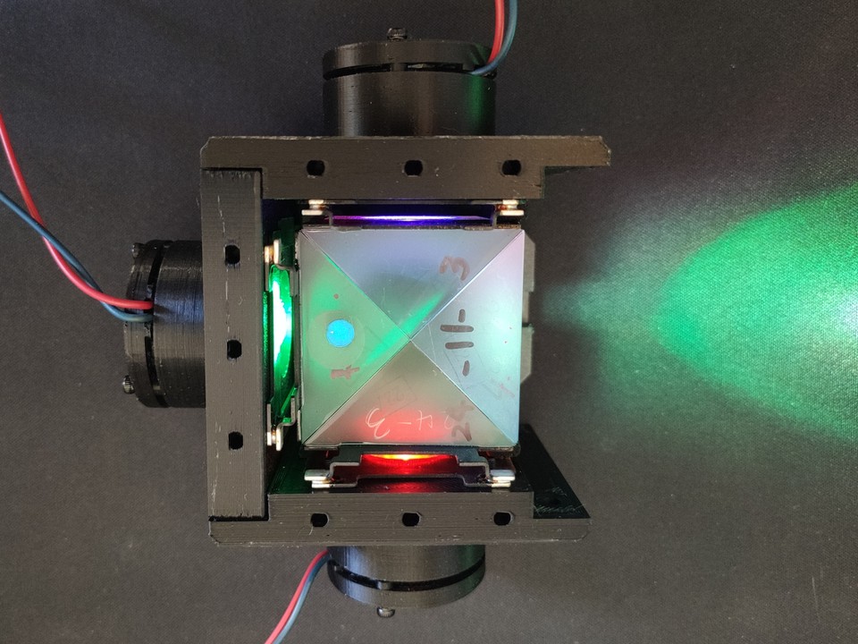
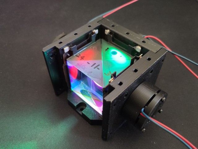
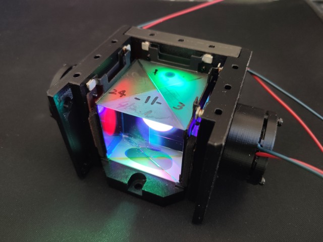
X-Cube from a dead Sony VPL X1000 3-LCD Projector
I’m using the LED housing design from the PUMA project. This is an easy and modular way to get a colimated beam from a 3W LED.
Monochromatic illumination
Using a narrow-band multiplexed RGB light source rather than traditional white light significantly improves image quality:
- Higher saturation
- Interferences are much more visible
- Better quality on the blue channel when using achromat objectives
However, despite these advantages, pixel crosstalk through the Bayer filter will still degrade image quality.
Sequential Illumination
A solution to this problem is to light only one LED at a time, capturing an image for each color channel separately (R, G, B), and then merging them into a final color image.
Although this method is roughly three times slower, it offers several benefits:
Independent exposure control
It’s possible to set independent exposure/gain settings for each channel to compensate for differences in brightness between each LED.Multispectral imaging
It is possible to replace each LED by other wavelengths compatibles with the X-Cube. For example purple, cyan, yellow.Suppression of Chromatic Aberrations
When paired with focus stacking and channels alignment, this technique allows to fully correct any chromatic aberrations.Ability to use a monochrome sensor
When paired with a monochrome camera, this method produces full-color images without the drawbacks of a Bayer filter.
Pixel crosstalk
Because of pixel crosstalk using multiplexed RGB instead of combined monochromatic RGB will result in lower contrast and saturation.


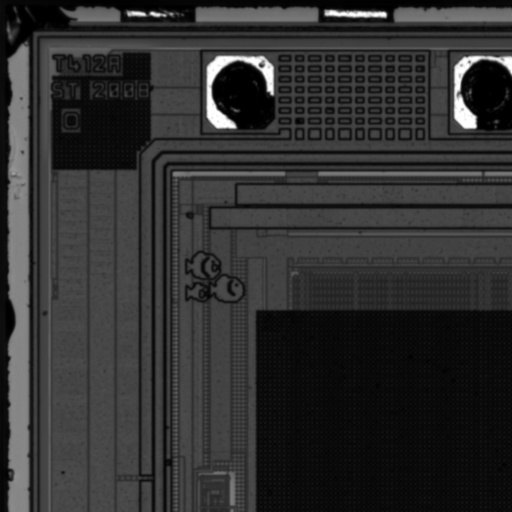
Results are similar without narrow bandpass filters.


But for highly contrasted samples, latteral chromatic aberration and chromatic aberrations can lead to clearly visible ghost artifacts.
Important note: The Nikon CF Plan EPI 10x used here don’t match well with the BH2-MA tube lens and we get a lot of chromatic aberrations.
| 1- White | 2- Wide | 3- Wide | 4- Narrow | 5- Narrow |
|---|---|---|---|---|
| Blue channel | Blue channel | Blue mono | Blue channel | Blue mono |
 |  |  |  |  |
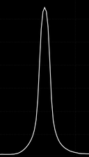 | 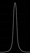 | 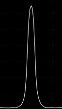 | 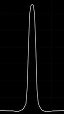 | 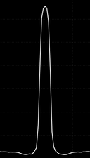 |
| Cropped area from the center of the field of view (almost no lateral chromatic aberrations). | ||||
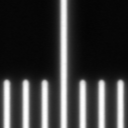
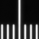
| 1- White | 2- Wide | 3- Wide | 4- Narrow | 5- Narrow |
| Blue channel | Blue channel | Blue mono | Blue channel | Blue mono |
 |  |  |  |  |
 | 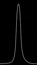 | 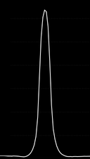 | 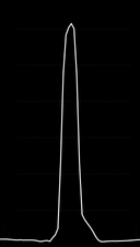 | 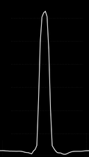 |
| Cropped area from the left of the field of view (with lateral chromatic aberrations). | ||||
White LED, blue channel only.
We can see a lot of halo caused by chromatic aberrations.RGB wideband LEDs, blue channel only.
Like with the white LED, but less halo.Blue wideband LED, monochromatic light.
Almost no more halo. Monochromatic light is very effective to remove aberrations.RGB narrowband LEDs, blue channel only.
No more halo, but ghost image of lateral chromatic aberrations.Blue narrowband LED, monochromatic light.
No more halo/ghost.
More details about the LEDs
LEDs used are Royal Blue, Deep Green and Deep Red.
Here the spectrum through the color camera. We can clearly see the IR cut filter in action at 665nm.
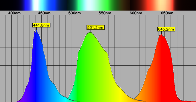
Wideband RGB illumination spectrum.
Here the spectrum of the narrowband illumination. Narrow bandpass filters are used in combination of the previous LEDs.
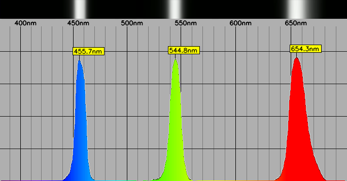
Narrowband RGB illumination spectrum.
Limitations
Because most of the light is blocked by filters:
Exposure times must be considerably longer.
The narrower the band, the less light will pass
Making it challenging to maintain sufficient brightness at magnifications above 20x where a tighter aperture is required.
I’m using different filters for high N.A. objectives, with 25-30nm FWHM instead of 10-15nm.
Leave a Comment